The adjustment of load distribution of electronic weighing sensor directly affects the weighing characteristics and other performances of weighing instrument. This paper introduces the adjustment method of the load distribution of the electronic weighing instrument, which adopts the support installation and multiple load cells in parallel.
Most electronic weighing instruments use multiple resistance strain type load cells, which can be installed in two ways: supporting type (pressure type) and hanging type (pull type), usually adopting supporting type.
When the load cell is used, its structure type, measurement characteristics and other technical and economic indexes should be correctly selected according to the selection principle to achieve the requirements of the best performance price ratio. After the installation of the weighing apparatus, it is necessary to adjust the parts and the whole machine. One of the main tasks is to adjust the load distribution of multiple load cells, which is generally called to adjust the force consistency of the sensors. As the electronic weighing instrument uses multiple sensors, the output mode of series and series parallel connection is no longer applied in practice. This paper introduces the inspection and adjustment method of load distribution by taking several resistance strain weighing sensors installed and used in parallel as examples. The adjustment of load distribution of load cell installed by hanging type can also be referred to.
1、 Basis and precondition of load distribution adjustment of load cell
Electronic weighing instrument is a kind of measurement method of mass (weight) which is established by using the principle of non electric measurement and converting mass (weight) into electric quantity through weighing sensor.
The basic requirements of the electronic weighing instrument for the used weighing sensor are: the output electric quantity is linearly corresponding to the input weight (mass) single value; it has the required accuracy and high sensitivity; it has better frequency response characteristics and less inertia; it has little influence on the state of the weighed object; it can work under the poor environment conditions; it has good stability, reliability and long service life.
The adjustment of load distribution of multiple weighing sensors of electronic weighing instrument can reduce the influence of "static indeterminacy" problem of balance of multiple fulcrum of weighing platform, ensure the stability of weighing platform support, so as to ensure that the center of gravity of weighing platform remains unchanged and the load-bearing transmission is correct, and ensure the accuracy of weighing instrument and relevant measurement performance requirements.
The precondition of load adjustment of load cell is mainly to check and adjust the installation quality of each part of weighing apparatus, to meet the technical requirements of technical standards, verification regulations, construction drawings and other technical documents, and to put forward the necessary parts and their characteristics. For the newly installed weighing instrument, all parts shall be inspected comprehensively, and only the inspected parts and the changed parts shall be inspected during maintenance.
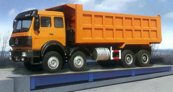
1. Platform structure
In addition to meeting the measurement performance and use requirements, the platform shall have symmetry of platform structure and uniformity of self weight distribution.
2. Weighing instrument system
The weighing instrument system is tested to be qualified according to the required technical indicators.
3. Selection and connection of load cell
In addition to meeting the performance index required by the weighing instrument, the load cell shall be selected with the same output sensitivity and input and output impedance as far as possible, and shall be correctly connected in the junction compensation box. Terminal compensation box
It may be installed near the weighing instrument in the metering room.
4. Output sensitivity re compensation of load cell
Various compensations have been carried out in the manufacturing of load cell, including output sensitivity compensation. But in many sensors used in electronic weighing instrument, the output sensitivity of each sensor can not be completely equal. When the supply bridge voltage is equal, the weighing error can not be ignored. Therefore, the actual bridge supply voltage of each sensor varies according to its sensitivity, that is to say, it needs to output sensitive re compensation in use.
Multiple sensors output in parallel, usually using a power supply for the bridge. When the sensitivity of the sensor is re compensated, the selection method of the actual bridge supply voltage is as follows: if the sensitivity Si of the ith sensor is the smallest among multiple sensors, and the bridge supply voltage UI is taken as consistent with the given bridge supply voltage range, then the actual bridge supply voltage UJ of the jth sensor with the sensitivity Si is determined by the following formula:

It is usually realized by adjusting the potentiometer symmetrically connected in series in the input circuit of the sensor in the junction compensation box.
5. Eliminate or reduce the influence of sensor transmission cable and various interference factors
The false signals generated by the sensor transmission cable and various interference factors affect the correctness of load distribution adjustment, so measures must be taken to eliminate and reduce them. In order to avoid the influence of the transmission cable, the quality, length and wiring of the cable are strictly required; the cable quality is good, the insulation resistance between the lines is more than 10m Ω, the sensor has high insulation resistance to the ground, the sum of the insulation resistance between the sensor and the bridge power supply to the ground is more than 200m Ω; the DC and AC parameters such as the cable resistance value, temperature coefficient and distribution capacitance are the same; the calibration (verification) and the length of the cable are the same It is required that the fixed length of the used sensor cable is the same; when the cable is not long enough in actual use, the cable consistent with the sensor shall be used for continuous wiring, welding shall be adopted instead of plug connection, and protective measures shall be taken at the welding position; the wiring shall be correct to avoid the influence of electromagnetic interference; the cable shall have shielding layer and the shielding grounding technology shall be used correctly to achieve the shielding effect; and Ratio measurement long line compensation technology, especially when the cable is long, is necessary; and so on.
6. Sensor support height adjustment device
In addition to the use of base plate with step height adjustment device, it is better to have two-sided adjustment special cushion block and other stepless height adjustment device, or fine adjustment device. If there is no stepless height adjustment device, thin base plate can be prepared. During the initial installation of stepless height adjustment device, the height shall be placed at the zero position of the positive and negative adjustable range.
7. The initial levelness, elevation and relevant dimensions of the scale platform installation are important factors to judge the installation of the scale platform and the sensor, not only to meet the technical status requirements specified in the technical documents, but also directly affect the load distribution on the sensor.
2、 Inspection and adjustment of load distribution of load cell
Under the premise of load distribution adjustment of load cell, check and adjust the load distribution.
1. Output value (zero point output) when the sensor is empty
Because the bridge supply voltage UB of the sensor during calibration (verification) may not be the same as the bridge supply voltage u in use, and after the output sensitivity re compensation, the actual bridge supply voltage UI is determined. Therefore, the no-load output value EOI of the actual bridge supply voltage can be calculated according to the no-load output value eiob when the sensor is calibrated (verified)

The output value of the sensor at no load can also be measured on site; lift the weighing platform with a jack, and measure the output value EOI of each sensor at no load in the junction compensation box with a weighing instrument or a high-precision digital voltmeter. The author thinks that the actual measurement method is more accurate and practical.
2. Output value of the sensor under the self weight of the weighing platform

3. Adjustment of sensor load distribution
"Adjust the supporting points of the scale one by one so that the load on the sensor has at least 20% f indication.". It is pointed out in document 2 that "the output voltage of the four sensors should be basically the same, each of which is about 1 / 4 of the dead weight". Through practice, we think that under the self weight of the weighing platform, the relative error between the output added value of the sensor and the output average added value is ± 5% - ± 10%, and the higher the accuracy of the weighing instrument, the more careful the adjustment should be.
Compare the output added value of each sensor under the self weight of the weighing platform. If the output added value and the average added value and the relative error of a sensor are less than the required value, or the output added value is far less than the average added value or even no output added value, use the sensor's stepless height adjustment device for adjustment, or use a jack to lift the weighing platform, and use a thin pad for adjustment and elevation Sensor support height: if the relative error between the output added value and the average added value of a sensor is greater than the required value, or the output added value is far greater than the average added value, the stepless height adjustment device of the sensor is used to adjust and reduce the sensor support height; the two methods of raising the sensor support height and reducing the sensor support height can also be applied at the same time. When the self weight of the scale platform is lighter or the adjustment requirements are higher, loading adjustment or verification can also be carried out. If. Sensors are used, the standard weight which is approximately equal to the maximum scale is placed in the middle of the scale platform for adjustment or verification. When adjusting or checking the load, the symmetry of the geometric position of the load on the platform is required to ensure the uniformity of load distribution of the sensor.
The above checks and adjustments may need to be repeated until the load distribution consistency requirements are met. Use stepless height adjustment device or thin base plate to adjust the load distribution of the sensor. Generally, the height of the scale platform changes slightly, and the elevation of the scale platform will not be out of tolerance if it does not exceed 1mm.
Tel:0757-26619568 Fax: 0757-26619508
24-hour online technical support:13790092618
Cloud platform:www.puliangiot.com
Social networks: